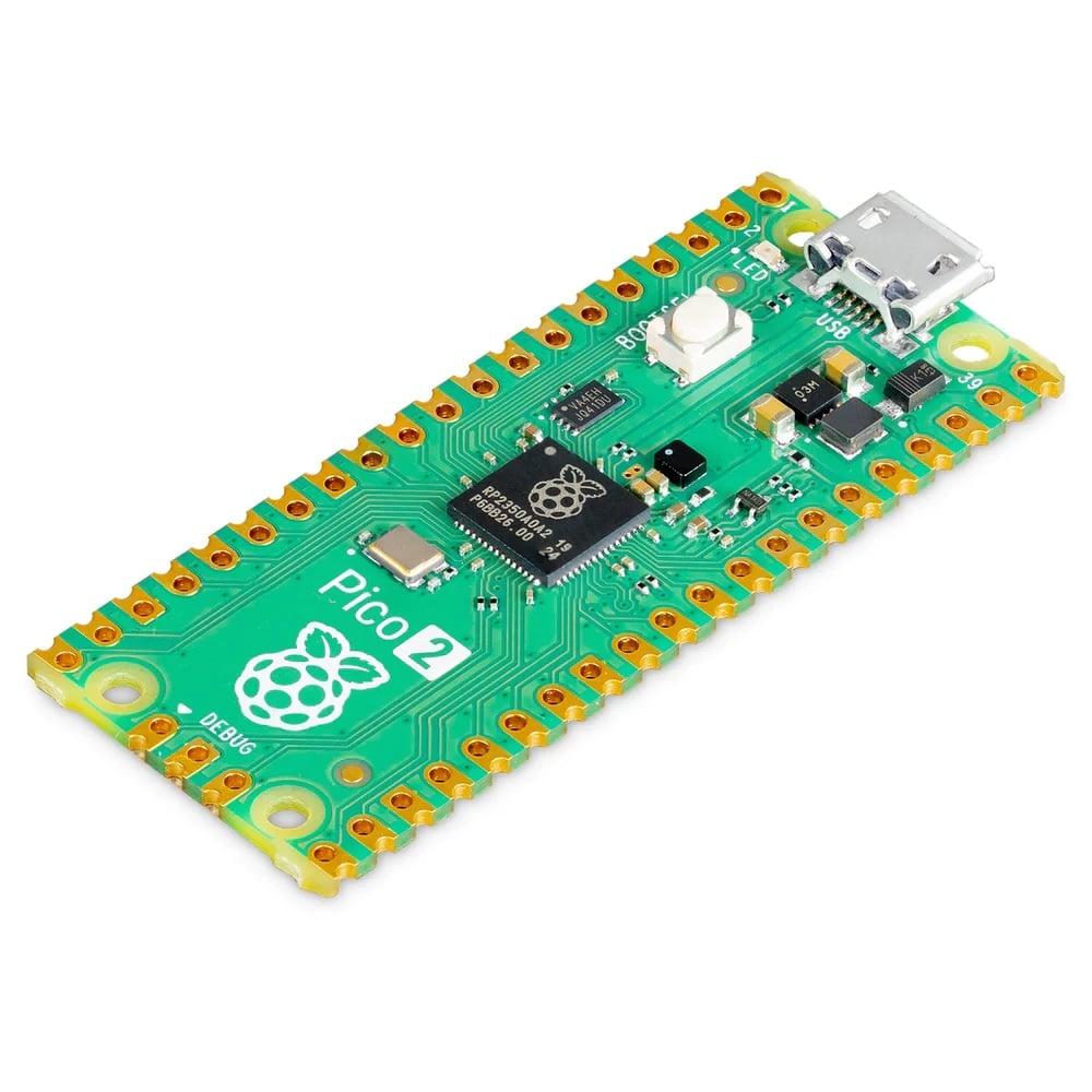
MCU / Controller


Pin compatible with Pro Micro 32u416MB flash memory26 GPIO pins (2 SPI, 2 I2C, 2 UART, 3 12-bit ADC, 16 controllable PWM channelsDimension: 18x33mm (0,71 x 1,3 inch)
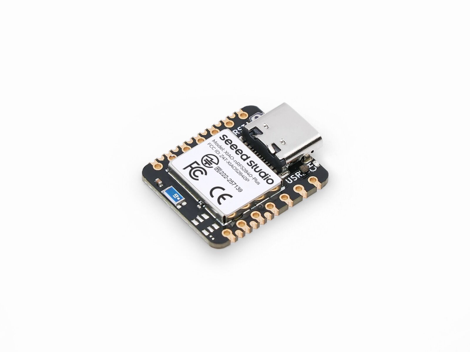
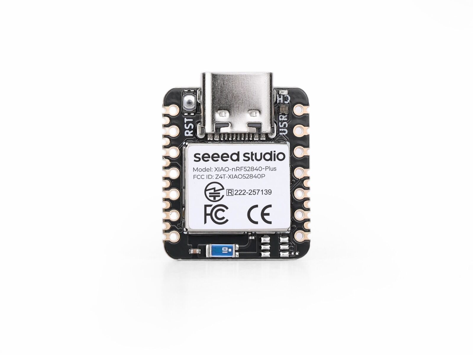
Seeed Studio XIAO nRF52840 Plus, powered by Nordic chipset with FPU, brings more SMD pins to our popular Bluetooth-enabled board. While maintaining all the capabilities of the standard version including Bluetooth 5.0, NFC, and low power consumption, this Plus variant features redesigned castellations and pad layout on the back, offering 9 additional GPIOs specifically for advanced Bluetooth projects requiring expanded I/Os via SMD board-to-board soldering. Please note Seeed Studio XIAO Plus doesn‘t come with 7-pin headers as it's designed for SMD board-to-board soldering.High-Performance MCU: Nordic Semiconductor‘s nRF52840 chip with FPU at 64 MHz, multiple development ports, compatible with Arduino/CircuitPython/MicroPythonAdvanced Wireless Connectivity: Bluetooth 5.0 with built-in antenna and NFC supportEfficient Power Management: 5 μA deep sleep consumption with integrated Li-ion battery chargingExpanded 20 GPIOs: 9 extra 1.27mm pitch SMD castellation pins beyond standard XIAO nRF52840Universal Compatibility: Standard backside layout (with aligned battery pads, and debugger pads) for more to-be-released XIAO expansion boardsClassic XIAO Form Factor: 21 x 17.8mm design with 2.54mm pin headers, single-sided mounting for wearables and space-constrained projectsXIAO Accessory Add-ons Compatibility: Natively compatible with all the XIAO accessory add-ons of expansion, connectivity modules (LoRa, CAN_Bus, RS-485), sensors (2-Mic Array, Vision AI, mmWave Motion, Environmental sensing), and actuators (ePaper display, LED Matrix, relay and more).Getting Started with Seeed Studio XIAO nRF52840 Series | Seeed Studio WikiSchematicNordic nRF52840 Data SheetPCN-XIAO Series Packaging Upgrade.pdf Item Seeed Studio XIAO nRF52840 Seeed Studio XIAO nRF52840 Plus Seeed Studio XIAO nRF52840 Sense Plus Processor Nordic nRF52840, ARM® Cortex®-M4 32-bit processor with FPU, 64 MHz Wireless Connectivity Bluetooth 5.0/BLE/NFC Memory 256KB RAM,1MB Flash 2MB onboard Flash Built-in Sensors N/A 6 DOF IMU (LSM6DS3TR-C), PDM Microphone Interfaces 1xI2C, 1xUART, 1xSPI 1xI2C, 2xUART, 2xSPI, 1xI2S PWM/Analog Pins 11/6 20/6 Onboard Buttons Reset Button Onboard LEDs 3-in-one LED/ Charge LED Battery Charge Chip BQ25101 Programming Languages Arduino/MicroPython/CircuitPython
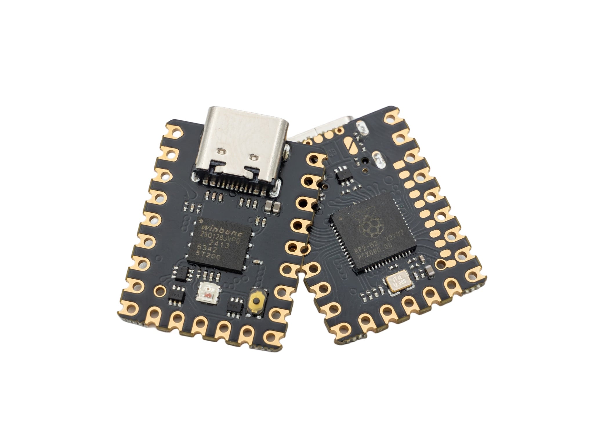
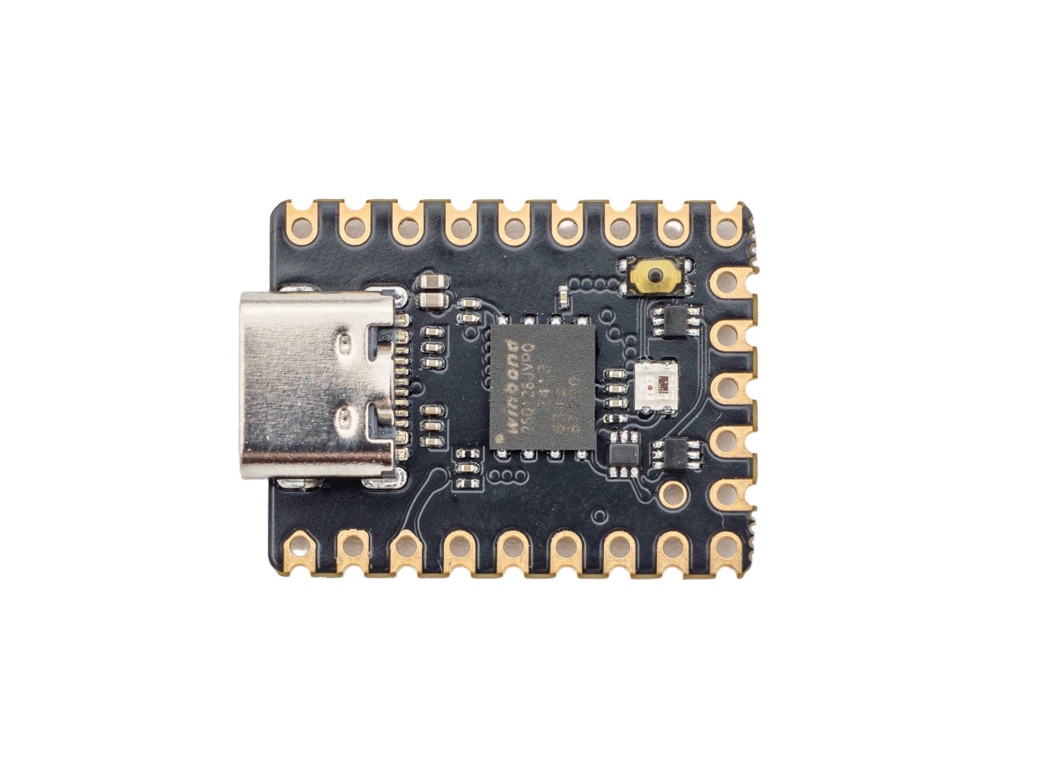
The 0xCB Gemini is our Waveshare RP2040-Zero compatible microcontroller.It includes all the features of it's bigger brother, the 0xCB Helios, in a much smaller form factor. QuickStartGitHub Included contents: 1 x 0xCB Gemini The Gemini comes without header pins, to keep the price low as possible.I highly reccommend to use the "Single Row Sockets" from Mill-Max, the cheaper alternative, or the "Spring-loaded pin headers".You can find the standard pin header here.
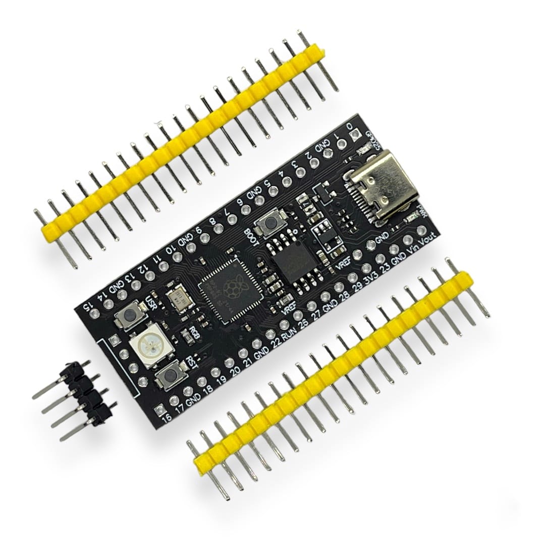
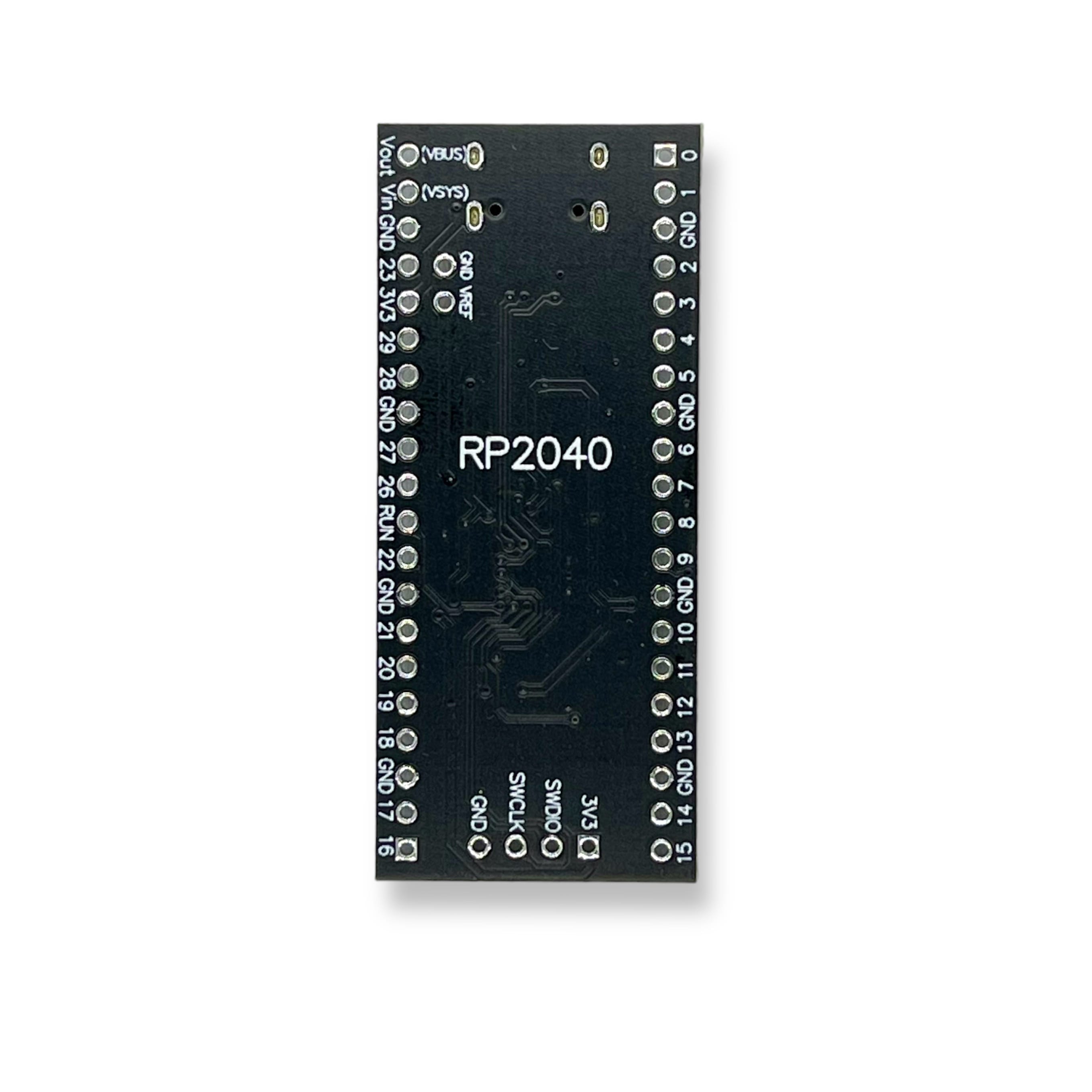
RP2040 microcontroller 16MB memory (W25Q32) USB-C WS2812 RGB LED (GPIO23) Boot, reset and user button Power LED, User LED (GPIO25) Pin VIN is different from the RaspberryPi Pico (VCC on Pico) Not compatible with Piantor PCB/Kit Flash firmware: Connect the board with a USB cable Press and hold the BOOT button Press and release RST button Release BOOT button A USB mass storage device with the name RPI-RP2 should apprear Drag and drop you firmware file (UF2)
Currently not available
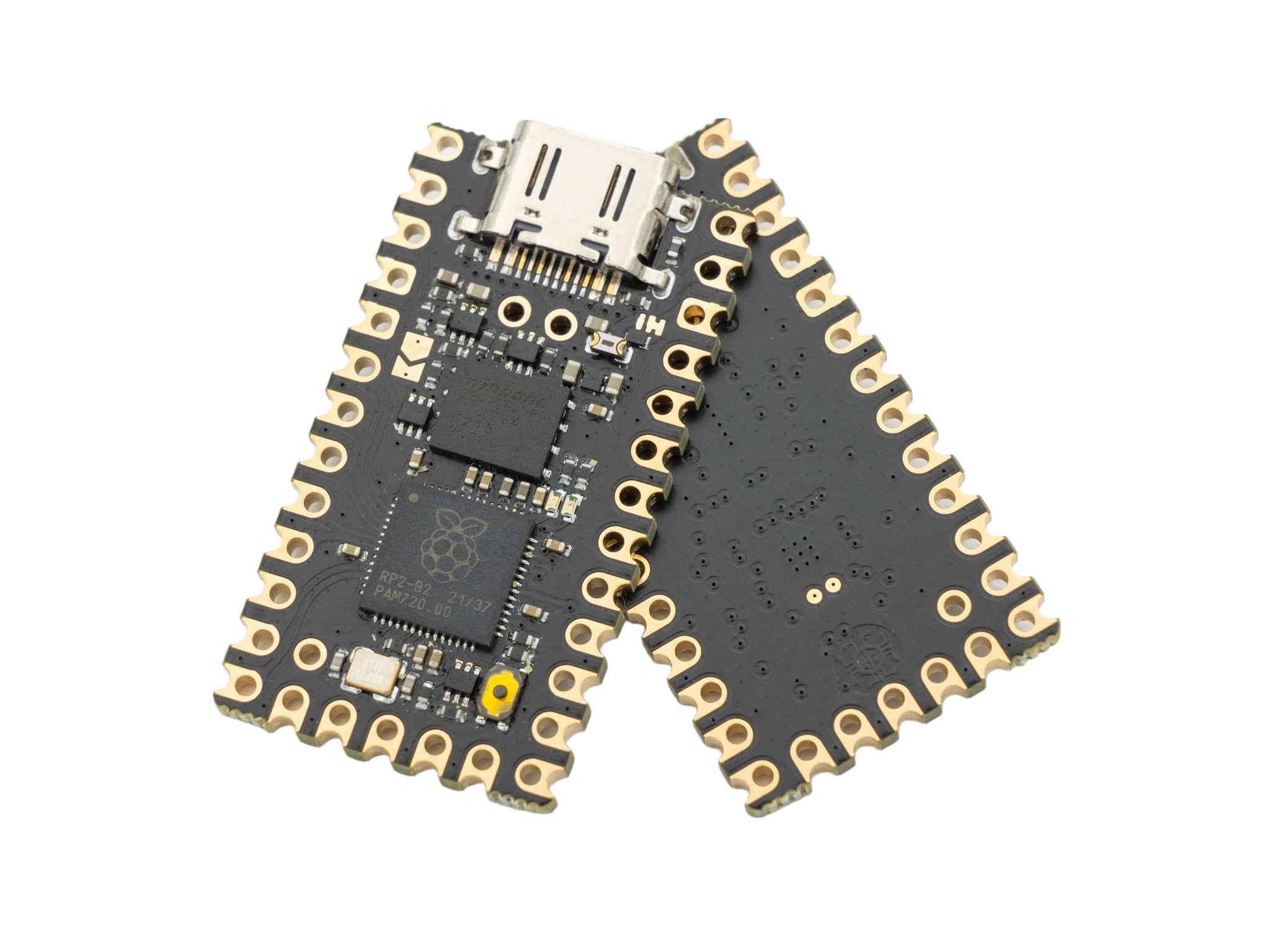
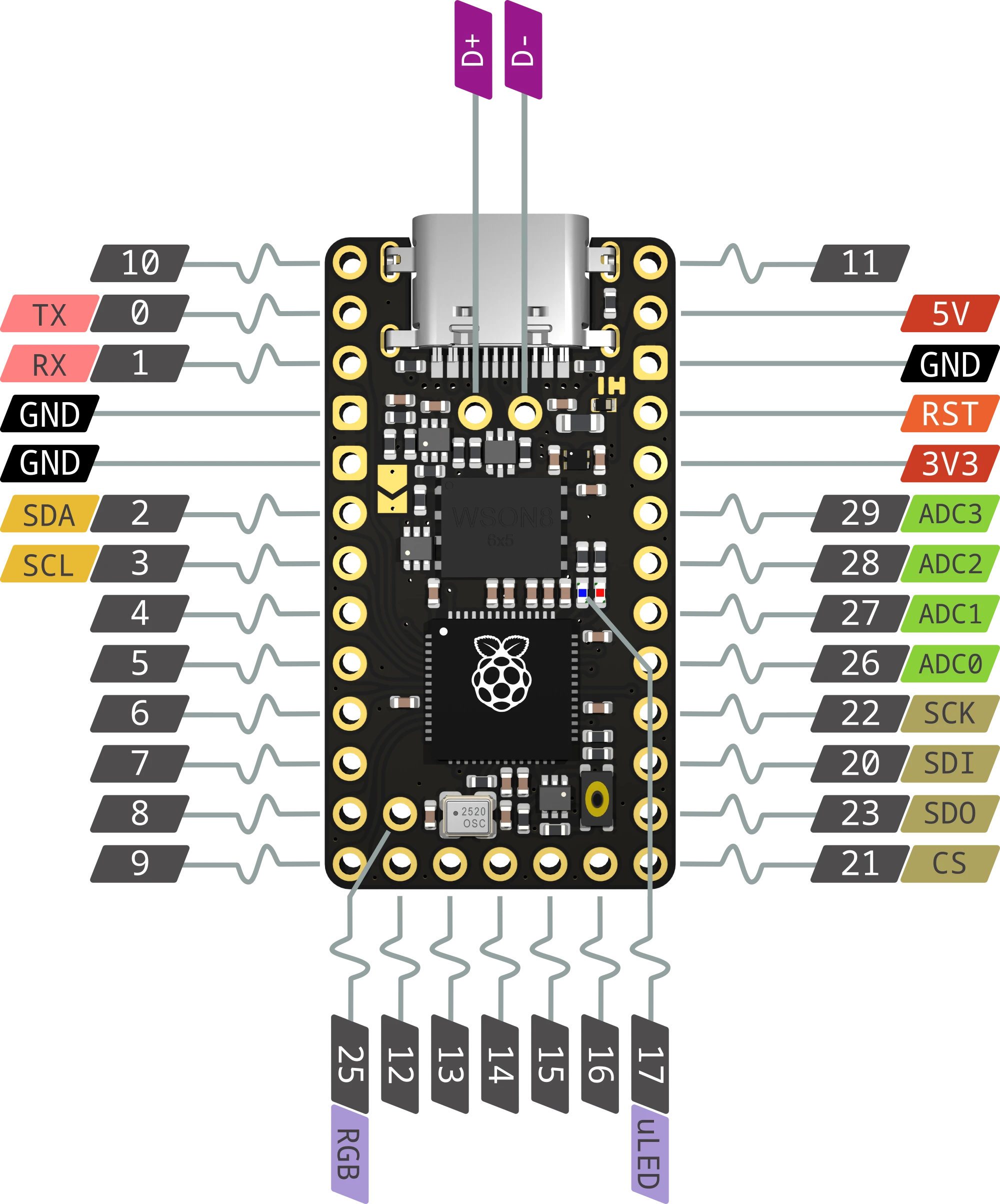
Meet Helios, the RP2040 Controller with Pro Micro/Puchi-C/Elite-C compatible pinout, 16MB (128Mbit) of flash, Dual ARM Cortex-M0 @133MHz, and 264kB SRAM. ESD protection chip onboard Supports VBUS detection for split keyboards You can select VBUS instead of raw for the 5V pin to hook up an external USB port with the included D+ and D- pads while maintaining ESD protection. A default off red power LED that can be turn on via a jumper Blue user LED Level-shifter to drive 5V components Single button reset circuit which enables you to reset the board with a short click Enter the bootloader with a long (>500ms) click Open-source by 0xCB The Helios comes without header pins, to keep the price low as possible.I highly reccommend to use the "Single Row Sockets" from Mill-Max, the cheaper alternative, or the "Spring-loaded pin headers".You can find the standard pin header here. Example to compile the QMK firmware for the Helios (uf2 file, not hex).qmk compile -kb crkbd/rev1 -km via -e CONVERT_TO=helios
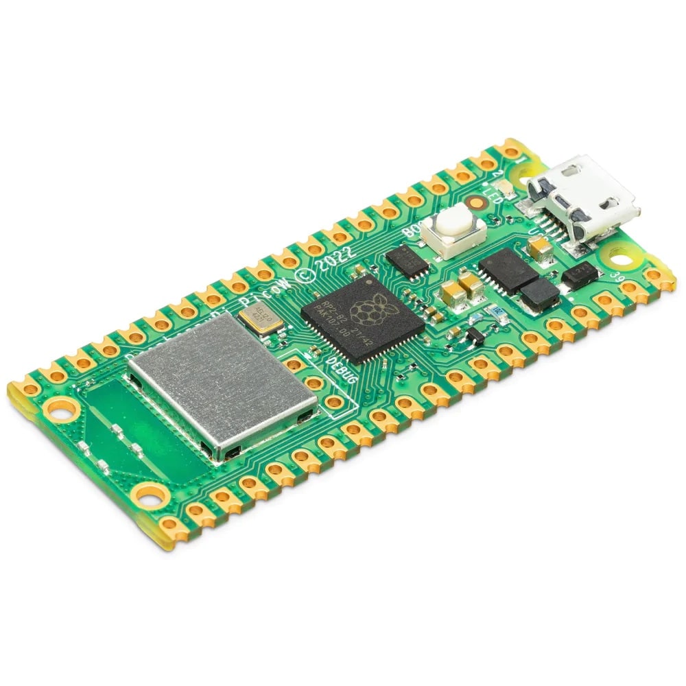
Following the hugely popular Raspberry Pi Pico, the new Raspberry Pi Pico W is a wireless-enabled version of the RP2040-based board, adding 2.4GHz 802.11n WiFi connectivity!At the heart of the Pico W is the RP2040 – the same chip used in the original Raspberry Pi Pico, featuring two ARM Cortex-M0+ cores clocked at 133MHz; 256KB RAM; 30 GPIO pins; and a broad range of interfacing options. This is paired with 2MB of onboard QSPI Flash memory for code and data storage.WiFi is enabled via the use of an Infineon CYW43439 wireless chip. The CYW43439 supports IEEE 802.11 b/g/n wireless LAN, and Bluetooth 5.2; however only wireless LAN is software-supported at launch.With the same footprint and same RP2040 chip, this WiFi Pico can be used as a drop-in replacement for your existing Raspberry Pi Pico projects, upgrading them with WiFi. This is the unsoldered version. It comes without header pins so you'll need to pick some up separately if you're planning on plugging your Pico into into a breadboard or one of our Raspberry Pi Pico add-ons. Documentation Raspberry Pi Pico W Specifications The main chip on board is the RP2040 made by Raspberry Pi (their first in-house microcontroller chip!) and is a dual-core ARM Cortex M0+ processor, with a flexible clock running up to 133MHz. WiFi is enabled via the use of an Infineon CYW43439. RP2040 microcontroller chip designed by Raspberry Pi in the United Kingdom Dual-core ARM Cortex M0+ processor, flexible clock running up to 133 MHz 264kB of SRAM, and 2MB of onboard Flash memory Infineon CYW43439 wireless chip IEEE 802.11n wireless LAN Bluetooth 5.2 (not software supported at launch) WPA3 SoftAP (up to 4 clients) Onboard antenna licenced from ABRACON (connected via SPI to the RP2040) Castellated module allows soldering directly to carrier boards USB 1.1 Host and Device support Low-power sleep and dormant modes Drag & drop programming using mass storage over USB 26 multi-function GPIO pins 2×SPI, 2×I2C, 2×UART, 3×12-bit ADC, 16×controllable PWM channels Real-time clock (RTC) Temperature sensor Accelerated floating-point libraries on-chip 8×Programmable IO (PIO) state machines for custom peripheral support Dimensions (WxLxH): 21mm x 51.3mm x 3.9mm Weight: 4g
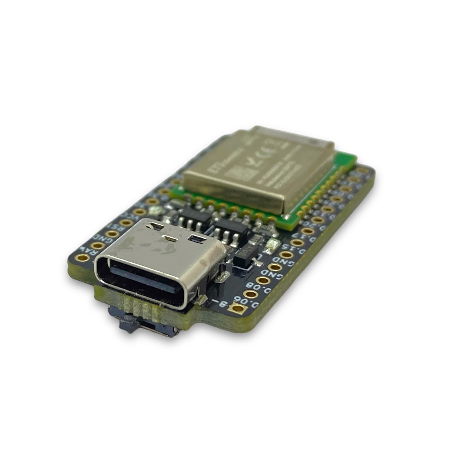
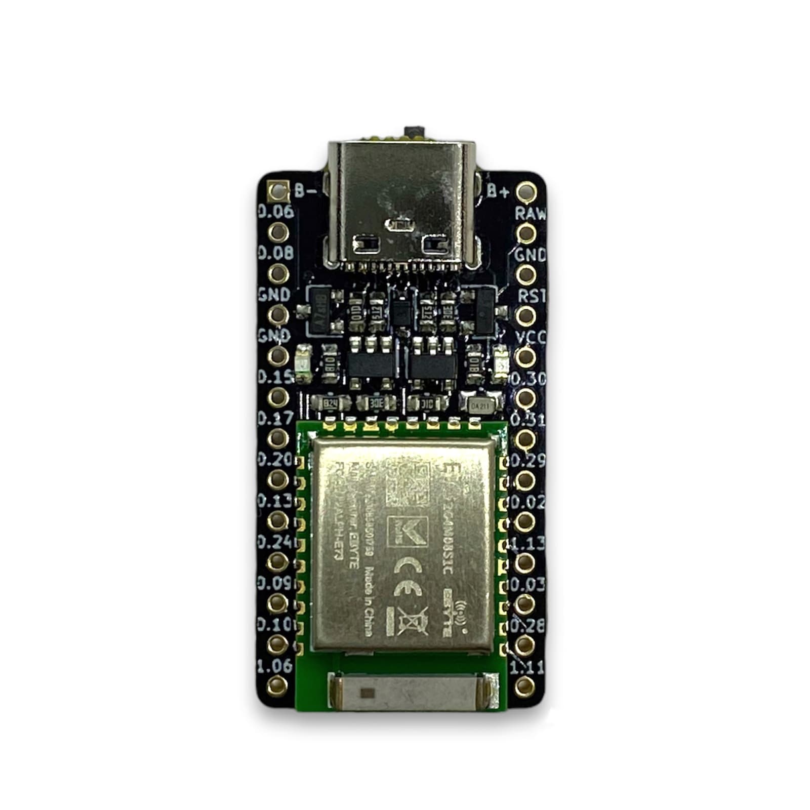
Features nRF52840 wireless module Li-Po battery charger (4.2V Lithium @ 100mAh) USB Type-C (data and charing) Pro-Micro drop-in replacement (same size 18x33mm, pinout) Support for QMK (nrf52 fork) and ZMK (recommended) USB Mass Storage for firmware update True wireless split keyboard (no TRRS cable, or separate receiver) Also wired split keyboard with USB-C and Serial/I2C connection Comes with Adafruit nRF52 Bootloader (UF2 Mass Storage updates and DFU serial) System requirements: Bluetooth >4.2 for ZMK Documentation Variant: Standard (thin): Mid-Mount USB-C connector, castellated holes, pattern on the backside With On/Off switch: On/Off switch for battery, higher as the Standard variant The Puchi-BLE comes without header pins, to keep the price low as possible.I highly reccommend to use the "Single Row Sockets" from Mill-Max, the cheaper alternative, or the "Spring-loaded pin headers".You can find the standard pin header here. Difference to the nice!nano: Certified Bluetooth module (CE, FCC and ROHS) Optimised ceramic antenna for high signal strength and low levels of interference On/Off switch to extend battery life (only Variant with switch) Open Source Battery (read carefully) Puchi-BLE supports 1S LiPo batteries (4.2V) Only use LiPo batteries with a protection circuit, because the Puchi-BLE has no low voltes (discharge) protection for batteries A 301230 (3.0 x 12 x 30 mm) LiPo batterie fit between 4.5mm tall pin sockets Connect the batterie to B+ and B-, or RAW and GND (these pairs of pins are internally connected) Avoid reverse polarity (nRF52840 chip is usually destroyed first) Note that a few keyboards have RAW and VCC pins connected together (namely Helix and Gherkin), and will kill the controller (RAW pin is for the charger only). You may just not solder RAW pin to the keyboard as a workaround. FAQ Do i need a TRRS cable to connect the split keyboard halfs? No, the slave side connects wireless to the master side. Optional you can use a cable (no charge over TRRS cable). What's the battery life? Approximately 2weeks with a 100mAh battery (no oled, or led‘s). Is there a lag while typing? Bluetooth devices can reach a latency of 1.3 ms. Lower latency means more power drain and reduce the battery life. Is it possible to switch between Bluetooth devices? Yes, QMK and ZMK have support for up to 5 Bluetooth profiles. What batteries work with the Puchi-BLE? LiPo batteries with 1S. Also important is that the LiPo batterie has a protection circuit (low voltes / discharge) Are batteries available in the shop? No, due to the german law, i don’t offer batteries in the shop. You can get LiPo batteries on Ebay and Aliexpress. What are the EXT_VCC and EXT_GND? Are they the same pins as VCC and GND? Yes. Power output is sofware-controlled to save battery (RGB LEDs draw up to 1 mA each when off). Does the magnetic USB-C adpater work with both variants?Yes. The switch does not collide with the magnet adapter. The Puchi-BLE is heavily based on the open source project nRFMicro from Joric.For each Puchi-BLE sold, a small amount is donated to the creator. Controller comparison BoardMCUArchitectureClockFlashRAM Puchi-BLE nRF52840 32-bit Cortex M4 64 Mhz 1 MB 256 kB nice!nano nRF52840 32-bit Cortex M4 64 Mhz 1 MB 256 kB Pro Micro ATmega32u4 8-bit AVR 16 Mhz 32 kB 2.5 kB Bluepill STM32F103C8T6 32-bit Cortex M4 72 Mhz 64 kB 20 kB Proton-C STM32F303CCT6 32-bit Cortex M4 72 Mhz 256 kB 40 kB Pinout
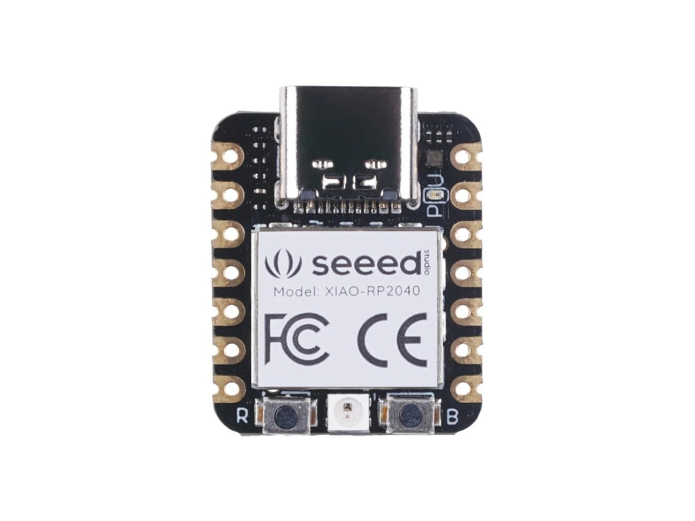
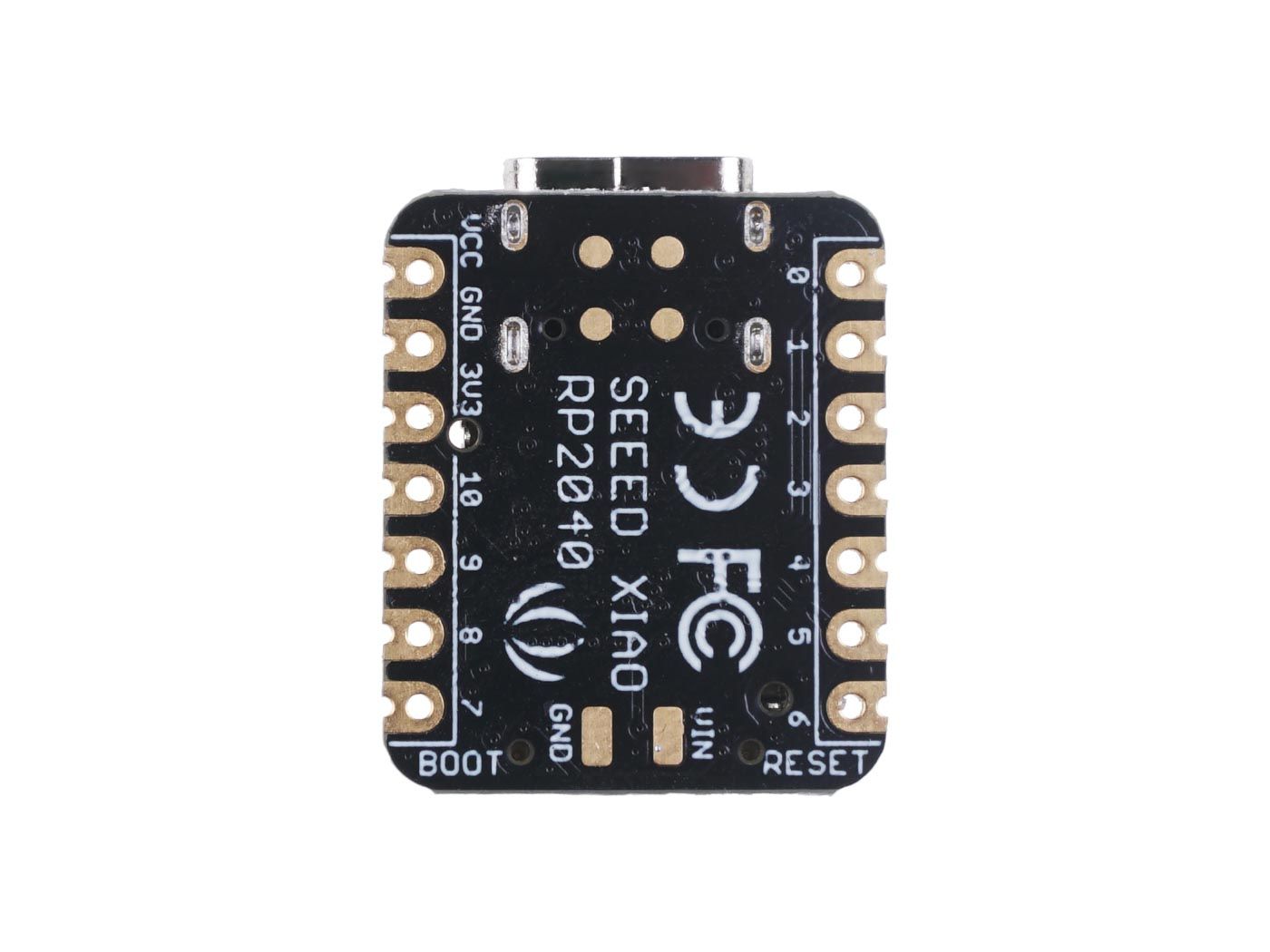
XIAO RP2040 Seeedstudio Wiki (with Schematic, Footprint, ...) All the I/O pins are 3.3V, please do not input more than 3.3V, otherwise, the CPU may be damaged. Parameter Description CPU Dual-core ARM Cortex M0+ processor, flexible clock running up to 133 MHz Storage 264KB of SRAM, and 2MB of onboard Flash memory I/O PINs 11 digital pins, 4 analog pins, 11 PWM Pins Interface 1 I2C interface, 1 UART interface, 1 SPI interface, 1 SWD Bonding pad interface Power supply & Downloading interface USB Type-C interface LEDs: 1 user LED, 1 power LED, two LEDs for serial port downloading, 1 RGB LED Button 1 RESET button, 1 BOOT button Power Pads For the battery power supply Software compatibility Support Micropython / Arduino / CircuitPython Cover Projection cover for protecting the circuit Dimensions 20x17.5x3.5 mm XIAO nRF52840 Seedstudio Wiki site (with Schematic, Footprint, ...) All the I/O pins are 3.3V, please do not input more than 3.3V, otherwise, the CPU may be damaged. Item Seeed Studio XIAO nRF52840 Processor Nordic nRF52840 ARM® Cortex®-M4 with FPU run up to 64 MHz Wireless Bluetooth 5.0/NFC/Zigbee On-chip Memory 1 MB flash and 256 kB RAM Onboard Memory 2 MB QSPI flash Interface 1xUART, 1xIIC, 1xSPI, 1xNFC, 1xSWD, 11xGPIO(PWM), 6xADC Dimensions 21 x 17.5mm Power Circuit operating voltage: 3.3V@200mA Charging current: 50mA/100mA Input voltage (VIN): 5V Standby power consumption: <5μA
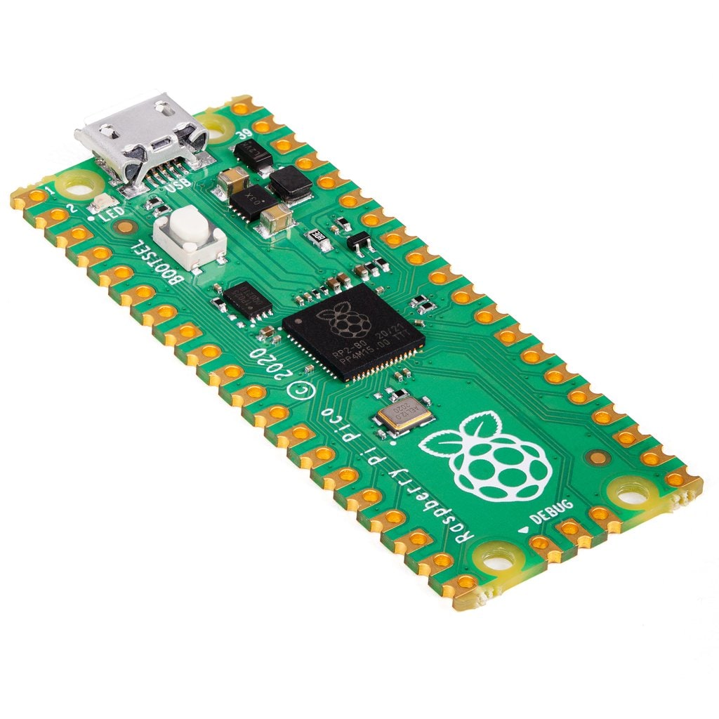
A low cost, high-performance microcontroller board built around Raspberry Pi's very own chip - the RP2040. Raspberry Pi Pico is Raspberry Pi's first microcontroller board, designed especially for physical computing. Microcontrollers are a different type of device than Single Board Computers (like the Raspberry Pi Zero and previous generations of Pi), they don't run an operating system and they are typically programmed to do just one task - though that task can be pretty intricate and exciting! They're perfect for experimenting with hardware and using as the brains of custom devices, machines and inventions. It can be easily reprogrammed over USB from a Raspberry Pi or other computer using the C/C++ SDK or the official MicroPython port. The landing page is the best place to get started, or scroll down for links to the technical documentation for both the Raspberry Pi Pico microcontroller board and the RP2040 microcontroller chip. This is the unsoldered version. It comes without header pins so you'll need to pick some up separately if you're planning on plugging your Pico into into a breadboard or one of our Raspberry Pi Pico add-ons. Board Specifications Raspberry Pi Pico is a low-cost, high-performance microcontroller board with flexible digital interfaces, built on silicon designed at Raspberry Pi. Key features include: RP2040 microcontroller chip designed by Raspberry Pi in the United Kingdom Dual-core ARM Cortex M0+ processor, flexible clock running up to 133 MHz 264kB of SRAM, and 2MB of on-board Flash memory Castellated module allows soldering direct to carrier boards USB 1.1 Host and Device support Low-power sleep and dormant modes Drag & drop programming using mass storage over USB 26 multi-function GPIO pins 2×SPI, 2×I2C, 2×UART, 3×12-bit ADC, 16×controllable PWM channels Accurate clock and timer on-chip Temperature sensor Accelerated floating point libraries on-chip 8×Programmable IO (PIO) state machines for custom peripheral support Documentation Documentation for the Raspberry Pi Pico board and the RP2040 microcontroller: Raspberry Pi Pico Datasheet - An RP2040-based microcontroller board RP2040 Datasheet - A microcontroller by Raspberry Pi Hardware design with the RP2040 - Using the RP2040 microcontroller to build boards and products Getting Started with Raspberry Pi Pico - C/C++ development with the Pico and other RP2040-based microcontroller boards Pico C/C++ SDK - Libraries and tools for C/C++ development on the RP2040 microcontroller Pico Python SDK - A MicroPython environment for the RP2040 microcontroller The API level Doxygen documentation for the Raspberry Pi Pico C/C++ SDK is available as a micro-site. Handwiring Keyboards with Pi Pico: 3x3 Macro Pad

